
Electric Angel
Introduction
Welcome to LRI electronics!The Electric Angel is LRI’s current avionics board, capable of measuring the necessary data for GNC and flight feedback. This documentation has multiple sections, which aim to explain the components used and their purposes in the board assembly, the organization of the schematics, and basic structure in the PCB editor. Each section has a high-level explanation (basic, general knowledge) and a low-level explanation (catered more towards specific details, [COMING SOON]), making it easier for anyone to understand.
Schematic
This page outlines the KiCAD schematic for Electric Angel. There are six pages in the KiCAD schematic, which sort out the following:
1. Root
- 1.a Power & USB
- 1.b Compute
- 1.c Sensors
- 1.d Connectivity
- 1.e Pyros
The organization of the schematic file sorts the components used on the board into five sections (pages), with the root page joining together the five sections. The root page may be treated as a general pinout for the components used and offers sufficient information to determine how pins are connected between components at a basic level.
Root
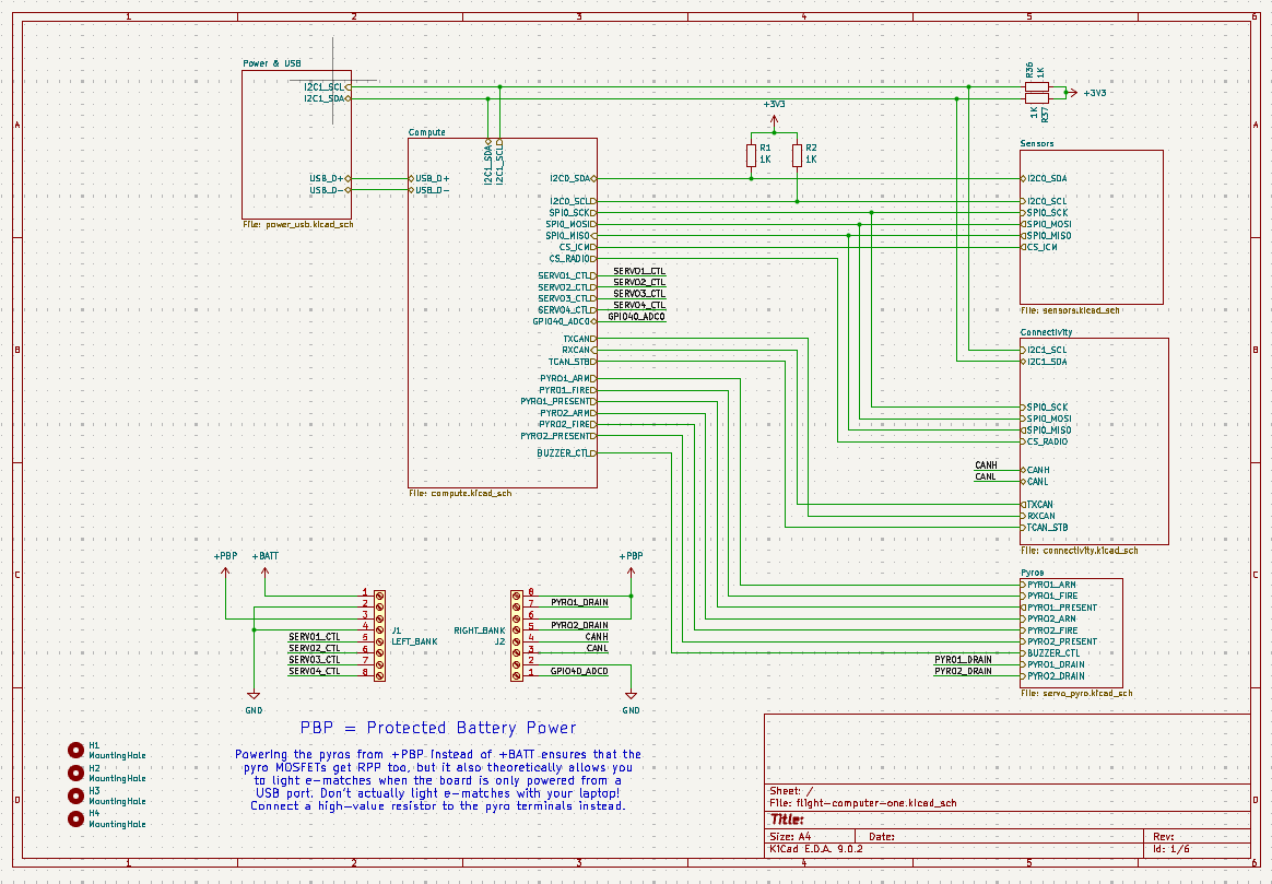
Diagram of the Root page in KiCAD Schematic Editor.
The Root page details the inputs and outputs of each subsystem on Electric Angel. The schematic above shows the pinout of the entire board where pins are used internally. At the bottom left is a diagram showing the wiring of the large pins coming out of Electric Angel, displaying four free control pins for servo motors, as well as two pyro drain pins, the CAN FD high and low pins, and an Analog-Digital-Converter pin (ADC), GPIO40. The orientation of the pins are set such that when Electric Angel is rotated with the printed image facing up, the pins are in an identical position to the schematic.
Power & USB
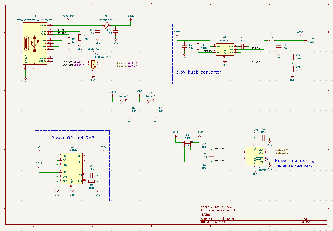
This page contains the components used for power management and USB connectivity. The following components were used in this portion, listed here from top to bottom, left to right:
USB-C Receptacle – USB2.0_16-Pin
TPS561246 – 3.3V Buck Converter
LED Setup
TPS2121 – Dual Input, Single Output (DISO) Power Multiplexer (MUX)
INA232 – I2C Output Digital Power Monitor
USB-C Receptacle – USB2.0_16-Pin
The USB-C Receptacle is a standard component which allows a USB C cable to be connected to Electric Angel. While the full USB-C connector has 24 contacts, the receptacle uses 16 active pins, not using the Super-Speed pins, providing USB 2.0 data rates and a simplified USB-C configuration. Apart from the data pins, the CC (Configuration Channel) pins are used to detect cable orientation, establish host/peripheral roles, and communicate available power capabilities. SBU pins, while present, are not active in this design. The VBUS pin has a raw output and a stabilized output available for external voltage readings to be taken.
Electric Angel also makes use of a USBLC6-2SC6 Transient Voltage Suppression (TVS) diode array, which protects the data lines of the USB input/output against electrostatic discharges (ESD strikes). This diode array is not strictly necessary but is utilized as a safety measure against occasional voltage spikes, static buildup, or electrical transients that could otherwise damage sensitive circuitry.
TPS561246 – 3.3V Buck Converter
The TPS561246 is a 3.3V converter which simply converts the PBP (Protected Battery Power) 5 volts to 3.3 volts, used by most of the components on the board. This component operates at 1.6 MHz and delivers up to 1 A of continuous output current.
LED Setup
The center details a simple LED setup, with one LED lighting up to indicate nominal 5V (VBUS) power output and the other indicating nominal 3.3V power output.
TPS2121 – Dual Input, Single Output (DISO) Power Multiplexer (MUX)
The TPS2121 allows for selection of either 3.3V or 5V output, based on those inputs. This module allows for seamless transition between USB power and an external power supply, for example from a battery. It can handle input voltages from 2.7-5.5V and supply up to 4.5A of current.
INA232 – I2C Output Digital Power Monitor
The INA232 power monitor operates via I2C protocols, and outputs voltage, current, and power values directly. By setting up I2C software, this module utilizes the output from the TPS2121 and PBP power, giving the three values.
Compute
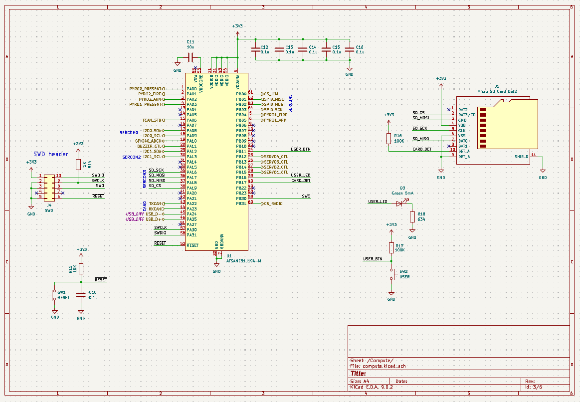
This page contains the components used for computation. Computation is the brain of Electric Angel, with an ATSAME51J19A-M 32-bit ARM Cortex-M4F microcontroller functioning as the main computational hardware. Including this microcontroller, the following components are used, listed here from top to bottom, left to right:
SWD Header Pins
ATSAME51J19A-M 32-bit ARM Cortex-M4F Microcontroller
Micro SD card slot
LED Setup
Reset and Boot Switches
SWD Header Pins
A simple pin array for debugging, allowing external connections. The pinout is indicated below: [IMAGE OF PINOUT]
ATSAME51J19A-M 32-bit ARM Cortex-M4F Microcontroller
This microcontroller runs the code and is the brain of Electric Angel. The board uses 3.3V logic and is thus supplied with 3.3V. All components which output and take in data are connected to the microcontroller, operating via Serial communications to send and receive data. To upload code, press and hold the boot button while uploading code. To reset the microcontroller and restart the running code, press the reset button. Both buttons are installed on the PCB.
Micro SD card slot
The micro-SD card slot allows an SD card to be put into the PCB for a robust and high-capacity mode of data storage, whether it be program outputted code or programs themselves. This component is of standard design, with four data output pins as well as power and ground.
LED Setup
A single green LED is used to indicate nominal operation of the microcontroller, connected to the dedicated USER_LED pin.
Reset and Boot Switches
Two buttons installed on the PCB, which when pressed, temporarily disconnects power until the buttons are released. The reset switch is connected to power and the dedicated RESET pin on the microcontroller, while the bottom switch is connected to power and the dedicated USER_BTN pin.
Sensors: [image]
This page contains the sensors in use on Electric Angel. Four of the sensors outlined below operate via I2C communication with the microcontroller, connected to I2C-capable pin pairs. The remaining sensor, the main IMU, operates with SPI protocols. It requires four pins for data instead of two. The outputs by these sensors give positional data (angular velocity, linear acceleration, orientation), dimensional magnetic field strength, local temperature and humidity, and local pressure readings. The following components are used, listed here from top to bottom, left to right:
BMI088 Backup Inertial Measurement Unit (IMU)
LIS2MDL Magnetometer
SHT40 Temperature and Humidity Sensor
MS5611-01BA Barometer
ICM-42688-P Main Inertial Measurement Unit (IMU)
BMI088 Backup Inertial Measurement Unit (IMU)
Two IMUs (Inertial Measurement Unit) allow the board to detect its angular velocity and linear acceleration, via built-in gyroscopes and accelerometers. This IMU is a backup IMU, a BMI088 which takes the same measurements as the main ICM-42688-P IMU. This IMU is more resistant to extreme conditions but has less accuracy.
LIS2MDL Magnetometer
The LIS2MDL Magnetometer takes measurements of the local magnetic field strength in microteslas. Within this section there is an array of capacitors connected directly from GND to 3.3V, this is a decoupling capacitor and helps to prevent voltage drops across the entire PCB when the sensors take measurements. This is a safety measure and ensures that the sensors do not interfere with other components and power.
SHT40 Temperature and Humidity Sensor
The SHT40 measure temperature and humidity of the immediate environment in Celsius and g/m^3 {Is this measured in percent too? Or is that part software}, respectively.
MS5611-01BA Barometer
The MS5611-01BA measures the air pressure of the immediate environment in kPA.
ICM-42688-P Main Inertial Measurement Unit (IMU)
The main IMU used on Electric Angel, allowing the board to detect its angular velocity and linear acceleration, via built-in gyroscopes and accelerometers. This IMU has the highest accuracy between the two IMU’s used, and thus is the preferred IMU. The unit does not communicate using I2C, instead utilizing SPI protocols. The IMU is connected to the microcontroller with four respective SPI-capable pins. Within this section there is an array of capacitors connected directly from GND to 3.3V, this is a decoupling capacitor and helps to prevent voltage drops across the entire PCB when the sensors take measurements. This is a safety measure and ensures that the sensors do not interfere with other components and power.
Connectivity: [image]
This page details the Electric Angel communications and connectivity components. The connectivity page handles data communication, external transmissions, and also acts as the data transmitter. The following components are used, listed here from top to bottom, left to right:
TCAN3404-Q1 CAN FD – Controller Area Network; Flexible Data-Rate
CAN FD is a protocol for data transfers. The TCAN2404-Q1 converts the TX/RX format of data on a microcontroller into CAN FD formats, outputting a high and low signal in respective outputs.
MAX-M10S – GNSS Receiver
The MAX-M10S is a module capable of receiving data from satellites above earth such as GPS, Beidou, GLONASS, and Galileo. These are satellite networks that measure positional data on the surface and allows Electric Angel to track where it is on Earth.
Ai-Thinker-Ra-01H COMM Radio Transceiver
The Ai-Thinker-Ra-01H allows long-range, low-noise data transfers between Electric Angel and external sources (i.e. mission control). It connects to other devices using an SPI protocol.
Pyros
The pyrotechnic setup on Electric Angel is customized, catering specifically to the operation and firing of the engines. The schematic here shows the wiring diagram:
[IMAGE]
An additional piezo buzzer is used. It makes noise.
KiCAD File
The KiCAD file of Electric Angel also includes a diagram showing the layers of the PCB itself. The components are wired exactly as in the schematic. It may be accessed by pressing the switch-view button, as shown here:

Layers may be navigated at the panel to the right, where Cu is copper, Adhesive sticks together layers, Paste represents soldering pads, [TODO (To learn)]