
Mini E-Box
Mini E-Box
The Mini E-Box (referred to as mE-Box from now on) contains all the electronic systems to control the solenoids and enables data collection from pressure transducers (PT(s)) present on the Phil Mk2 test stand. The mE-Box also houses the manual switches to actuate the solenoids. The e-box serves as a control system for the test stand, governing the flow of fluids while delivering real-time data to make quantitative measurements and assertions. The capabilities of the mE-Box are as follows:
- Actuates up to 2 solenoids using lever switches attached to the top of the mE-Box
- Collects and facilitates up to 2 PTs
- Interfaces with an Arduino Uno R3
- Runs code onto the Arduino in order to collect pressure data
- Interfaces with a 12V Battery
A simple electronics schematic depicting the connections in the mE-Box is pictured below in Figure 1:
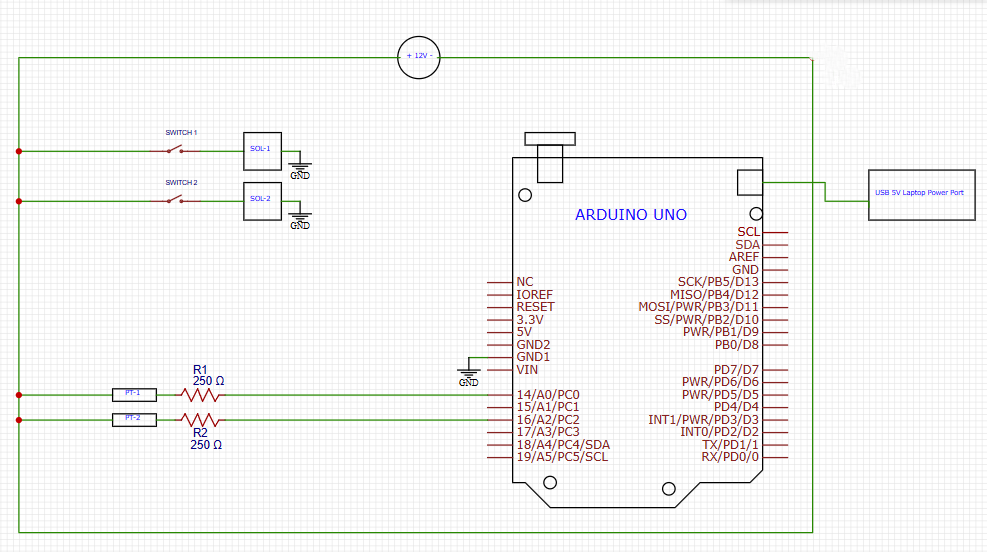
Figure 1: mE-Box Electronic Schematic
Design Decisions & Process
The mE-Box was created under significant time constraints, with the primary objective of testing Overture’s pintle injector the Phil Mk2 test stand. Because the test stand required only minimal functionality for initial operation (two PTs and two solenoid valves with no need for upgradability) the design prioritized compactness (hence the name Mini E-Box), speed of development, and ease of fabrication. This urgency meant that the design process was simple, focusing on immediate needs rather than extensive research or future expansion capabilities.
In terms of design methodology, only essential dimensional checks were conducted. Apertures and slots for connectors, switches, and boards were determined largely through manual measurements using calipers and scales. For certain critical components, such as the Arduino UNO R3 microcontroller and its mounting hole pitch, the manufacturer datasheet depicted in Figure 2 was consulted to ensure accuracy. This approach allowed for a rapid design process, while making sure the mE-Box was properly dimensioned.

Figure 2: Mounting Holes and Board Outline for an Arduino UNO R3
Pros and Cons
Due to the small form factor of the mE-Box, some modifications can be made to accommodate more PTs and/or other sensors, but it would be preferred to remodel an entirely new or switch to an existing larger e-box. However, the mini e-box fulfills the outlined requirements, and does so with minimal use of resources and time.
Design Iterations
The mini e-box went through only one major iteration, as the capability and functions of the e-box were decreased due to a lack of immediate need and time constraints. The original e-box had the following requirements:
- The basic shape of the e-box was to be either a cube or rectangular prism with an open bottom
- The e-box had to contain four slots which interfaces with PT connectors
- The e-box had to contain four slots which interfaces solenoid valve sockets next to the PT connectors
- The e-box had to contain four apertures, adequately spaced, to mount four lever-switches, which actuate solenoid valves, spread out in a horizontal line next to each other on the top face
- The e-box had to have sufficient space to stick two thin rectangular power distribution boards (PDB)
- The e-box had to have one slot which interfaces with a 12V Battery socket
- The e-box had to contain a slot for an Arduino UNO R3 microcontroller which interfaced with a laptop through an USB connection
- The e-box had to mount an Arduino R4 Minima microcontroller on the underside of the top plate
The original design is depicted below as a sketch in Figure 3

Figure 3: Schematic of original e-box design
The main iteration regarding the e-box was a scaling down of the box’s functionalities, with the removal of multiple interfaces for sensors and other components and the addition of a modular bottom. The revised and final requirements were as follows:
- The basic shape of the e-box was to be either a cube or rectangular prism with a modular bottom for easy access
- The e-box had to contain two slots which interfaces with PT connectors
- The e-box had to contain two slots which interfaces solenoid valve sockets next to the PT connectors (add exact part name for all)
- The e-box had to contain two apertures, adequately spaced, to mount two lever-switches, which actuate solenoid valves, spread out in a horizontal line next to each other on the top face
- The e-box had to have one slot which interfaces with a 12V Battery socket
- The e-box had to contain a slot for an Arduino UNO 3 microcontroller which interfaced with a laptop through a usb-c connection
- The e-box had to mount an Arduino UNO R3 microcontroller on the underside of the top plate
The final iteration consisted of fewer slots and interfaces for PTs, solenoid valve sockets and switches, along with the addition of a groove to slide in and out a modular bottom plate.
Subsystem Structure
Processing and Data Acquisition
The onboard microcontroller, the Arduino UNO R3, is a significant part of data acquisition. The UNO receives analog data from the PT, in a form of voltage, and converts it into ‘psi’ using the input code which is displayed on a serial log, allowing for collection of data.
Actuation
Two manual switches, control the actuation of the solenoid valves, one allowing pressurized fluid to flow into the pipe system and the other allowing the fluid to enter the pintle injector.
Power Management
A 12V Battery powers most of the mE-Box’s functions, powering the two PTs, two solenoids and their manual actuation switches, and the negative terminal of the battery acting as a common ground for the system. The onboard Arduino is sufficiently powered through an 5V USB port from a laptop.
How it works and Operating Procedure
ADD P&ID To support
Before you start
- Arduino connected to Laptop on USB
- 12 V battery available but disconnected
- Both solenoid valves are closed (connect battery and check if unsure)
Startup
- Load code onto the Arduino and open the serial to confirm live readings
- Power on by connecting the 12 V battery
- Tare sensors (zero): With the system vented (no pressure), tare PT1 and PT2. Readings should be ~0
Pressurize & verify
- Start logging (so all states are captured)
- Bring supply pressure up with V1 CLOSED, V2 CLOSED
- Expectation check: PT1 rises to the set supply/regulator pressure; PT2 ≈ 0
- If PT2 shows pressure here, V2 may be leaking
Flow sequence
- Charge the line: Set V1 = OPEN, keep V2 = CLOSED.
- PT1 ≈ supply pressure; PT2 should still be ~0 (no flow to injector yet)
- If PT2 rises now, V2 is not sealing (check before proceeding)
- Feed the injector: Set V2 = OPEN
- PT2 now tracks injector inlet pressure and logging remains automatic
Stop & secure
- Stop flow: Close V2, then V1
- Stop logging and save the file (test ID + timestamp)
- Depressurize per stand procedure (vent/regulator)
- Power down (disconnect 12 V and USB if finished)
Safety & quick diagnostics
- Any over-pressure, leak, or abnormal trend: CLOSE V2 → CLOSE V1 → vent safely
- Sanity checks by step:
- After pressurize (V1/V2 closed): PT1 > 0, PT2 ≈ 0
- After opening V1 only: PT1 > 0, PT2 ≈ 0
- After opening V2: PT2 > 0 and responds to flow changes
Maintenance
Due to the relatively simple design of the mE-Box, limited number of PTs and solenoid valves, as well as the lack of breakout and Analog-to-Digital Converter (ADC) boards, the mE-Box does not require almost any maintenance. The only concern would be damage to the microcontroller or loose wires during use, which should be checked prior to utilizing the e-box and are unlikely to be a cause for concern if all components are properly soldering and attached.