
RAND-E E-Box Technical Information
Technical Specifications
E-Box symbolic diagram for reference:
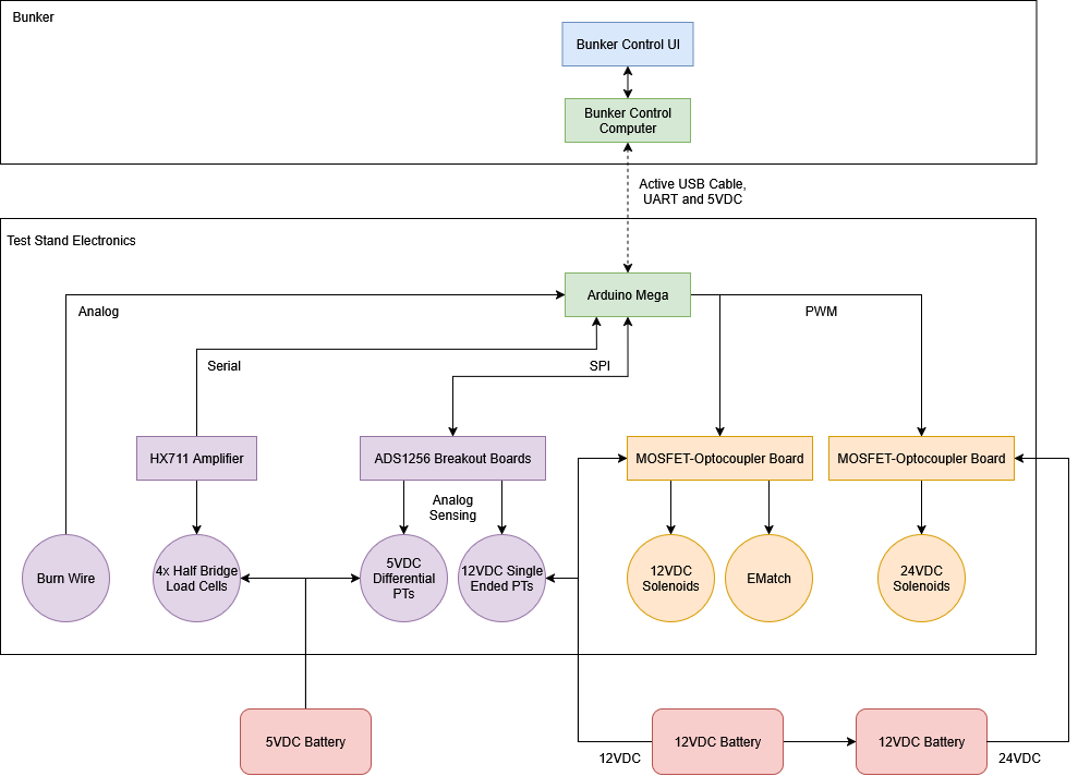
E-Box symbolic diagram
Microcontroller
For control, we are using a standard genuine arduino mega. All other components are connected to the arduino through various different protocols, and the onboard code directly interacts with all other subcomponents.
Code
The code repository can be found here. It follows the standard RCP target reference implementation, barring the additions for the system-specific technology. To build the firmware, ensure you also have the HX711 library installed. The library for interfacing with the ADS1256 ADC boards is included in the source tree.
On power on, the arduino will wait for a serial connection to be established before doing anything. Afterwards, all hardware peripherals and subsystems are initialized, and the RCP ready packet is sent. On each loop, autosequenced tests will be updated, RCP packets will be processed, then the transducers and load cells subsystems will be updated, which involved sending the appropriate RCP data packets back to the host computer.
Burn Wire Connection
The burn wire is connected directly to arduino pin A0, with the other end tied high.
E-Match
The E-Match is connected to actuator channel 0 on the top of the E-Box, and arduino pin 29.
Load Cells and Amplifier
The load cells are connected to the arduino through an amplifier, specifically the HX711. This chip responds over its own serial protocol, but one way or another it sends back the measurements for weight. One of the signal wires is connected to arduino pin 8, the other to pin 9. We aren’t sure which wire is for which function exactly, but if the load cell is returning weird, nonsensical data, try switching the wires to see if that fixes the issue. The amplifier/load cell array has been extremely consistent otherwise.
ADC boards and Pressure Transducers
Transducer Types
The test stand is using 2 different types of pressure transducers for pressure sensing. One variety has 3 wires (furthermore being referred to as “single ended”), 2 being for power and the last being a voltage output with reference to ground. The other has 4 wires (furthermore being referred to as “differential”), 2 for power, and 2 with a voltage differential indicating the output. This kind is basically identical to the 3 wire kind, except instead of the voltage output being referenced to ground, it is referenced to the 4th wire.
These transducers are of the differential variety:
- PT1-OX-PRS
- PT2-F-PRS
- PT3-OX-TNK
- PT4-F-TNK
These transducers are of the single-ended variety:
- PT5-ACT
- PT6-OX-PROP
- PT7-F-PROP
- PT8-IGN
Transducer ADC Channels and Pins
The exact ADC channels for each transducer (and for each connector on the box itself) are still somewhat up in the air, but these table summarizes which transducers are intended to go to which ADC channels and ports:
| Transducer # | RCP ID | ADC Board # | Board Channel(s) | Port |
|---|---|---|---|---|
| PT1-OX-PRS | 4 | 0 | 0/1 | Top Middle |
| PT2-F-PRS | 5 | 0 | 2/3 | Top Right |
| PT3-OX-TNK | 6 | 0 | 4/5 | Middle Right |
| PT4-F-TNK | 7 | 0 | 6/7 | Center |
| PT5-ACT | 0 | 1 | 2 | Top Left |
| PT6-OX-PROP | 1 | 1 | 1 | Middle Left |
| PT7-F-PROP | 2 | 1 | 0 | Bottom Left |
| PT8-IGN | 3 | 1 | 3 | Bottom Middle |
The ADC boards respond to the arduino over SPI, so as such they share several wires, which is what the small perfboard next to the two ADCs is for. Thus, the SCK, MISO, and MOSI pins are connected to the corresponding pins on the arduino. This table shows the rest of the pin assignments:
| Board # | Pin | Arduino Pin |
|---|---|---|
| 0 | CS | 7 |
| 0 | DRDY | 6 |
| 1 | CS | 5 |
| 1 | DRDY | 4 |
| 0/1 | PDWN | NC |
Additional Configuration
In the header file for the transducers (transducers.h), there are a few extra configuration options you can set. The first, SAMPLE_INTERVAL, sets the interval in milliseconds between successive samples. The other, AVERAGE_BUFFER_SIZE, sets how many consecutive samples to average together for the final results.
Solenoids and Actuator Boards
The two actuator boards are COTS boards which act as essentially a wrapper around a MOSFET. This allows the arduino’s low voltage GPIO pins to control the higher voltage higher current solenoids directly, without the need for a complex intermediary board. The following table lists the channel number/RCP ID for each solenoid, as well as the arduino pin it corresponds to:
| Solenoid # | Channel #/RCP ID | Arduino Pin |
|---|---|---|
| SV1-OX-PRS | 2 | 25 |
| SV2-F-PRS | 1 | 27 |
| SV3-OX-ACT | 6 | 24 |
| SV4-F-ACT | 5 | 26 |
| SV7-F-V | 3 | 23 |
| SV9-OX-ACT | 4 | 28 |
| SV10-OX-ACT | 7 | 22 |
Mounting
The box has 4 mounting brackets on the top and bottom used to screw it onto the test stand. Within the box, components are mounted with standoffs screwed in to heat set inserts.