
RAND-E Electronics Box
RAND-E E-Box
The RAND-E E-Box (just E-Box from now on) contains all of the control electronics for the test stand, and additional connectors to facilitate readings from transducers and load cells, and control to solenoids. In total, the E-Box has the following capabilities:
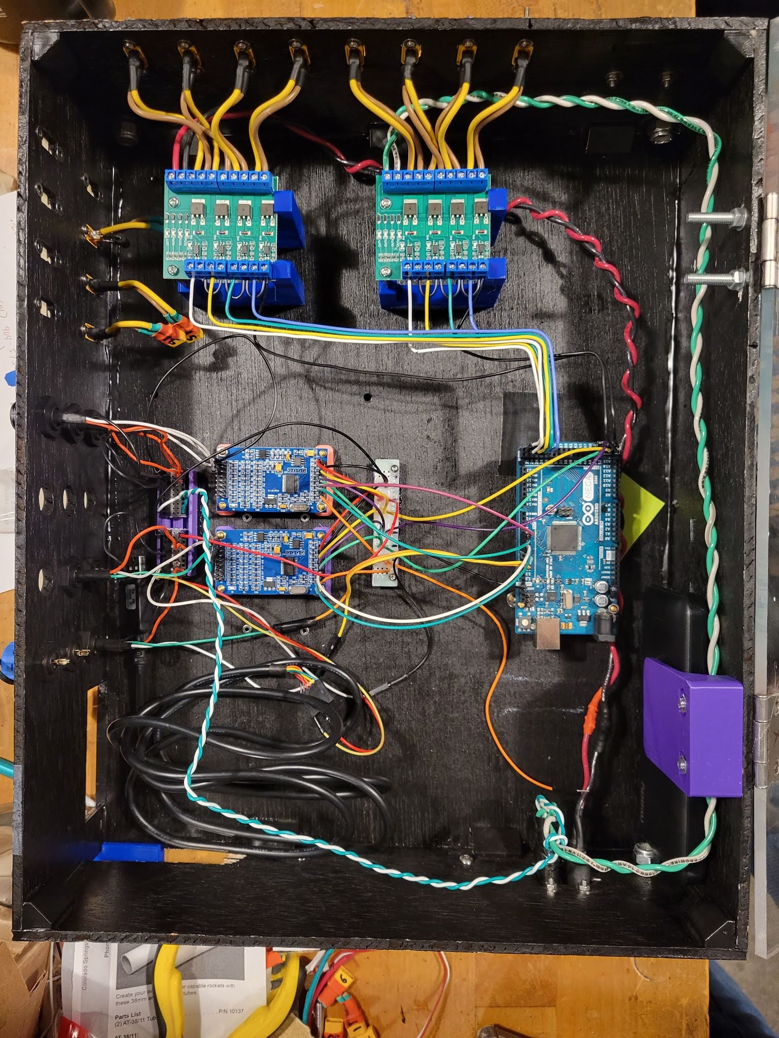
E-Box Close Up
- Running control code on the onboard Arduino Mega
- Controlling up to 8 solenoids
- Up to 8 differential pressure transducers, or 16 single-ended pressure transducers
- 1 Load cell array
- Interfacing with RCI to provide a graphical control interface
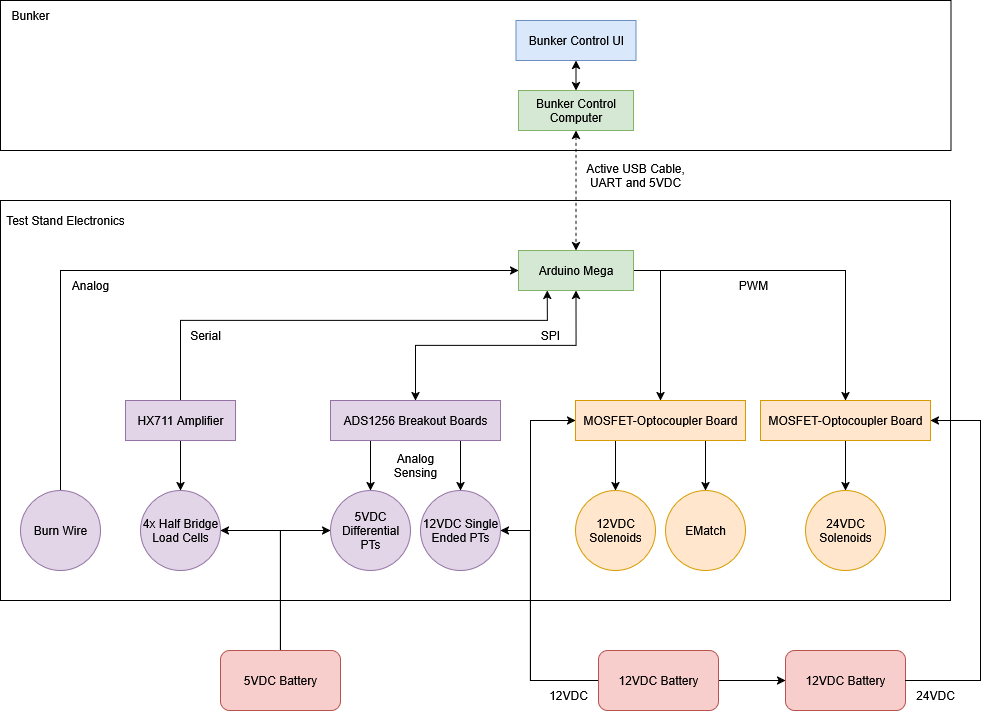
An overview of the whole electronics system looks as follows:
E-Box Flow Chart
Usage
In order to use the box, it must be supplied with both 12 and 24 volts, as well as a separate 5V power supply for the lower power pressure transducers. On the test stand, the 2 car batteries are used to achieve the 12V and 24V supplies, and a portable charging battery is used to supply the 5V. In the current configuration, the arduino is powered via the USB connection to the host computer. Once connected, RCI can be used to view sensor outputs, control actuators, and start automated tests.
Auto Tests
As of now, these are the supported automated tests:
- Solenoid Verification: Progresses through all 8 solenoid channels. For each channel, the test stand will enable that channel, and wait for human verification that the channel actuated. Once confirmation is received, the channel is disabled and the test moves on to the next.
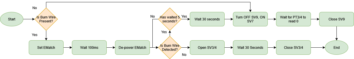
- HOTFIRE: This is the main hotfire test, as can be seen in the flow chart:
- SV3/4 ON: A helper test to turn both SV3 and SV4 on simultaneously
Ports
The sides of the box have various different ports for the components not inside the box itself:
- 16 connectors used to power the solenoids. The 8 connectors on the left side of the box are not connected. On the top of the box, the connectors are numbered starting from port 0 on the very right, to port 7 on the left
- 9 connectors for pressure transducer. 5 connectors have 3 pins for the single ended transducers, and 4 connectors have 4 pins for the differential pair transducers
- 1 connector for the load cell array
- 2 Connectors for power
Extra Information
You can find more technical information about the electronics box here, and a breakdown of some of the design decisions and issues here. In addition, there is an advanced usage guide with some more information on calibration and communication here.